Foc.us EEG Dev Kit is an electroencephalography (EEG) device, used for monitoring electrical activity of the brain. It measures voltage on electrodes, digitizes and streams via Wi-Fi or records into internal memory.
The Device can be controlled using one of following options:
There are two versions of EEG Dev Kit available
EEG Only Dev Kit can be used for EEG only. EEG+ Dev Kit as an addition to EEG functionality supports transcranial electrical stimulation (tES).
EEG Only Dev Kit Includes
EEG+ Dev Kit has all of the above plus
Device status indicator LED
Power button
Microphone
Power charge socket
tES electrode socket
“O” Daisy Chain socket
“W” Daisy Chain socket
Reference/bias electrode socket
Single-ended input channels 1 & 2
Single-ended input channels 3 & 4
Single-ended input channels 5 & 6
Single-ended input channels 7 & 8
Differential input channel 7
Differential input channel 8
fNIRS sensor socket
For charging, please, connect the power charger to EEG Dev Kit and then to mains. Blue indicator shows charging and switches to green color, when charging finished (charging indication works if device doesn’t perform any other actions). Also, you can check the battery level in Device Details menu.
Full battery charging normally takes 2-3 hours.
Note, that EEG session and tES can’t be enabled whilst device is charging. This is both for safety and quality of recorded signal.
EEG Dev Kit has two types of biopotential analog inputs: 1) single ended 2) differential.
Channels #1 to #6 are always single-ended.
Channels #7 and #8 are dual purpose and can be configured as single-ended or differential. It is important to ensure that the correct sockets are used according to the desired configuration.
Signals at single-ended input channels are referenced to a common ground. And this common ground (called reference input of the EEG Dev Kit) is shared between all single-ended inputs.
So, single-ended measurement is the voltage difference between input channel and reference.
Differential input channel consists of two lines: negative and positive. And differential measurement is the voltage difference between those lines.
Reference channel is a dedicated input line used for single-ended channels. And acts as common ground for single-ended measurements.
The EEG can be monitored with either a bipolar or a referential montage (using differential or single-ended inputs respectively). Differential channels requires two times more electrodes comparing to single-ended, so the referential montage is the most popular for EEG.
The right place for the reference electrode should be found. If possible, this place must be located in “inactive” zone (no brain activity), and also should not pick up signals which are not recorded (like heart activity). Usually this is the right or left earlobe.
Patient bias output is used for common mode rejection. Another name for it is driven ground. Or the right leg drive (RLD) – holdover from electrocardiography (ECG) technology.
The human body is prone to common-mode drifts because noise easily couples onto the human body, similar to an antenna. These common-mode drifts may push the input common-mode voltage out of the measurable range of the system.
There are several frequencies of interest, depending on the location and the country of operation. The primary source of interference is the AC main that generally operates at 50 Hz (Europe and Asia) or 60 Hz (USA). Apart from these two frequencies, Eastern European railway traction power networks use distributed single-phase ac power at 16⅔ Hz. A frequency of 25 Hz is used for the Austrian railway.
The bias circuit of the system senses the common-mode voltage of a selected set of input channels (can be configured in UI) and creates a negative feedback loop by driving the body with an inverted common-mode signal.
In EEG applications the bias electrode usually connected to the center of forehead, but can be placed anywhere on the body, since its location is irrelevant in most cases.
It is a pair of dry electrodes wired to a 3.5mm jack. Each electrode consists of a small printed circuit board (PCB) wrapped into conductive soft silicone. The silicone component has spikes to go thru hair when attached to head.
The main circuit of the active electrode is a unity gain amplifier to buffer very low level EEG signals. This model has advantages comparing to passive electrodes:
When connected to a single ended input of the main unit the electrode at short wire corresponds to the lower channel number and at long wire – to the higher channel number. E.g., if a pair of electrodes attached to socket “1 & 2”, then electrode at short wire is channel 1 and electrode at long wire – channel 2.
When connected to a differential input of the main unit the electrode at short wire corresponds to negative line and at long wire – to positive line of the input channel.
There is a special pair of electrodes with a clip at long wire and normal soft silicone electrode at short wire. It must be connected to “REF / BIAS” socket of the main unit. The electrode at short wire is a reference (see 3.1.Analog Biopotential Inputs) and at lone wire with a clip – bias (see 3.2.Device Analog Outputs).
There are 2 types of active electrodes: Dry Active EEG (black color) and Dry Active EEG+ (orange color) Electrodes. They come with EEG Only Dev Kit and EEG+ Dev Kit respectively. The difference that Dry Active EEG+ electrode has an extra circuit to disconnect electrode’s input. It is necessary when tES enabled and EEG electrodes left on head. So, EEG electrodes don’t create wrong paths for tES current.
If electrode is used with a third party EEG system, please, follow this specification:
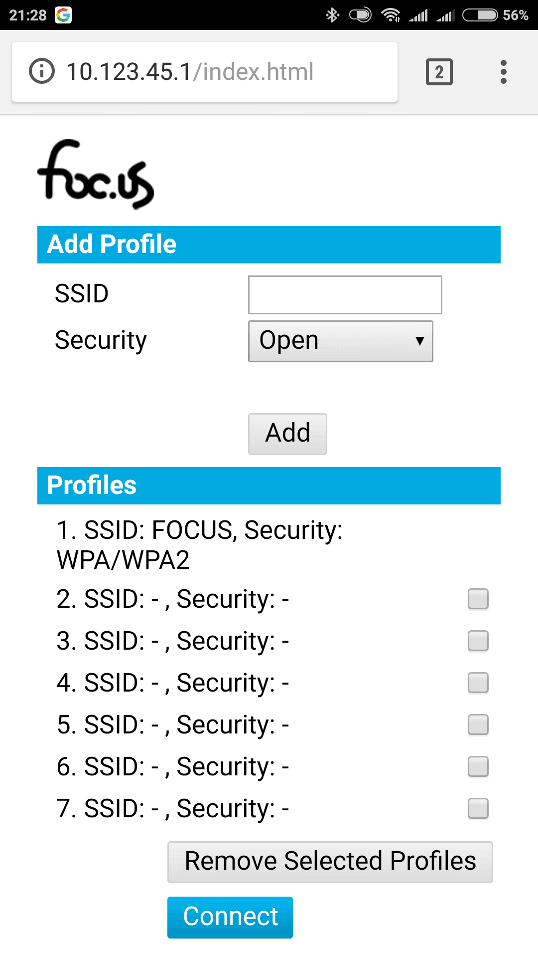
After turning EEG Dev kit ON, it attempts to connect to known Wi-Fi network(s) using details from saved Wi-Fi profiles. If it cannot connect in 30 seconds the device switches into Wi-Fi provisioning mode.
There are few methods to configure EEG Dev Kit to Wi-Fi access point (AP)/wireless router credentials:
For this method your access point/wireless router must have a physical or virtual (in web UI) WPS button:
Follow these steps:
Instead of configuring EEG Dev Kit you can configure your access point/wireless router to Wi-Fi credentials, preprogrammed to device:
This method is not recommended.
There are 3 options for EEG Dev Kit data output:
In “stream” mode device publishes data to server (broker) using MQTT protocol in real time.
MQTT is an Internet of Things (IoT) protocol, provides a lightweight method of carrying out messaging using a publish/subscribe model. EEG Dev Kit is a MQTT client, connects to a MQTT broker and publishes data at specific topic. The broker then pushes the information out to those clients that have previously subscribed to the client’s topic. So, any computer that runs a MQTT library can receive data from EEG Dev Kit in real time.
Please, refer to chapter 3.9 “Using Your Own Server” if you want to use your own MQTT broker.
In “file” mode device saves data into internal flash memory in EDF+ or BDF+ format (can be configured in UI). As soon as session finished it starts file uploading to FOCUS servers for storage. File can be downloaded to your computer at “Recorded Sessions” page. Note, that free storage is available for 7 days only, after that time the file will be deleted automatically.
The European Data Format (EDF) is a simple and flexible format for exchange and storage of multichannel biological and physical signals. Complete specifications can be found at official website https://www.edfplus.info/. EEG Dev Kit fully supports the newest extension – European data format ‘plus’ (EDF+).
BDF+ format, developed by Biosemi, is a 24-bit version of the EDF+. Its specification can be found here: https://www.biosemi.com/faq/file_format.htm.
EEG Dev Kit is a 24-bit EEG system. It is recommended to use BDF+ format to get full advantages. When using EDF+ the input voltage range is limited to ±732uV, comparing to ±187mV for BDF+.
For your convenience it is possible to fill EDF+/BDF+ field “local patient identification” in UI:
The foc.us EEG Dev Kit now includes native Lab Streaming Layer functionality. From firmware version 5.1.0 when you enable EEG channels, in either stream or stream & record modes, the device will create a lab-streaming layer on the wifi network.
Using LSL opens up a lot of software options for processing your raw EEG data. There is no software overhead or proxy involved as the device streams natively straight onto the network. This gives ultra-low latency times.
Currently this is limited to sample rates below 1k SPS but will be increased in a future update.
By default device streams data to FOCUS MQTT broker for EEG signals filtering and visualization in UI. If you want to get access to raw data you need to setup your own MQTT broker or use a third party one.
Note, that at this moment device supports transport layer security (TLS) only for connections to FOCUS MQTT broker.
Local MQTT broker is useful if you want to use maximum possible sampling rates (up to 16000 SPS). This is possible, because local network normally has very low latency. Another reason to use a local MQTT server could be safety, since in this case sensitive private data doesn’t leave your local network.
If you don’t have bash installed, follow these steps to install ubuntu subsystem on windows 10. Alternatively just install ActiveMQ on Windows.
Install Apache ActiveMQ and start it (instructions here).
The EEG Dev Kit will connect to your ActiveMQ server over your Wi-Fi connection. It is important that both devices are on the same network for this to work.
Then open firewall rules for any ports that are used in conf/activemq.xml e.g. 1883
Check that you can connect to your ActiveMQ using an MQTT client such as MQTT.fx
Another quick check is to use telnet from another machine on the same network
Your EEG Dev Kit has a unique 24 digit ID (Device ID) which can be found in foc.us/me Device Details page.
Create a topic in ActiveMQ with your Device ID plus suffix .afe.binary
e.g. 303730313534510A004A0024.afe.binary
Now provide the new server details to the Dev Kit in the focus/me Settings page
e.g. mqtt://192.168.15.43:1883
Finally turn on one or more AFE channels.
This is the simplest option to get access to raw data. There are many paid and free MQTT brokers. In this example we show, how to work with public MQTT broker https://test.mosquitto.org. Since it is public, there is even no need to create your own account.
To receive the raw data in real time any MQTT client can be used. It should be connected to MQTT broker and subscribed to ‘deviceID’/afe/binary topic.
Below, you can find, how to configure the MQTT.fx client to use MQTT broker from the previous example.
Everything is ready to receive data. Turn EEG session ON in UI.
EEG Dev Kit Device
Active dry electrode:
Power charger:
Indicator color | Number of blinks | Device state |
Blue | solid | Charging. |
1 | EEG session is ON. | |
Green | solid | Battery fully charged. |
1 | Device online. | |
2 | Device online and uploading file. | |
Orange | solid | Wi-Fi provisioning. AP mode (www.configure.dk). |
1 long | Wi-Fi provisioning. WPS push button mode. | |
1 | Waiting to connect to Wi-Fi. | |
2 | Connected to Wi-Fi, waiting for IP address assignment. | |
3 | IP address acquired. | |
4 | Network quality test passed successfully. | |
Red | 1 with button press | Empty battery. Connect charger. |
1 | Bad network quality. Try to reboot or connect to another Wi-Fi. | |
2 | Device offline. Try to reboot. | |
3 | Wi-Fi security failure (possible wrong Wi-Fi password) | |
White | fast flashing | Firmware is being updated. Do not remove the power. |
Can’t connect to WiFi?
Check following:
FOCUS is constantly working on adding new features (and fixing bugs). Your device is automatically updated if new version available. EEG Dev Kit checks for updates if battery is charged at least 50%, connected to Wi-Fi and power charger connected.
Current firmware version can be found on Device Details page in UI.
Please, don’t store device with empty battery. Be sure that it is charged to 50% at least. Otherwise battery life may be reduced significantly.
The packet contains multiple samples of raw data.
Default MQTT topic name: ‘deviceID’/afe/binary
Device ID can be found on Device Details page of the UI.
Offset | Size | Name | Note |
0 | 12 | Device ID | Unique for each device |
12 | 1 | Product ID | 1 – for foc.us EEG Dev Kit |
13 | 1 | Format version | 1 |
14 | 6 | Timestamp | Milliseconds since Epoch |
20 | 2 | Sample rate | Samples per second |
22 | 1 | Channels mask | 0bXXXXXXXX, X – channel ON(1)/OFF(0), LSB – Channel 1 |
23 | 1 | reserved | |
24 | 4 | Channel 1 value | Only if enabled. Type – float (uV) |
28 | 4 | Channel 2 value | Only if enabled. Type – float (uV) |
32 | 4 | Channel 3 value | Only if enabled. Type – float (uV) |
36 | 4 | Channel 4 value | Only if enabled. Type – float (uV) |
40 | 4 | Channel 5 value | Only if enabled. Type – float (uV) |
44 | 4 | Channel 6 value | Only if enabled. Type – float (uV) |
48 | 4 | Channel 7 value | Only if enabled. Type – float (uV) |
52 | 4 | Channel 8 value | Only if enabled. Type – float (uV) |
56 | 4 | Channel 1 value | Only if enabled. Type – float (uV) |
… | … | …. | … |
WE PROVIDE THE FOLLOWING PAYMENT
METHODS